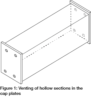
Where hollow sections are sealed they must be vented for reasons of safety so allowing the escape of air and the ingress and drainage of zinc during the dipping process. Vent holes are required at each sealed end either in the end plate or the section.
Where holes are provided in end plates they should be placed diagonally opposite one another, off centre and as near as is practically possible to the wall of the member to which the end plate is connected, which shows optimum venting with two sets of diagonal holes.
Where holes are provided in the member these should be diagonally opposite one another and as near to the end of the section as is practically possible.

Examples of good venting practice are shown in figures 2-4. Figure 2 illustrates vent holes positioned in the hollow section diagonally opposite one another. These are positioned as close as possible to the ends of the hollow section to prevent formation of an air lock or zinc trap.
If there are any doubts or questions, please contact your galvanizer.
Alternatives to vent holes include U or V notches, or grinding off the corners of square or rectangular hollow sections as this provides ideal locations for venting and drainage. Where these options are used it is important that they have equivalent surface area to the vent hole that would otherwise have been provided.

Every sealed section of a fabrication must be vented for reasons of safety and to allow access and drainage of molten zinc. Holes diagonally opposite each other should be as close as possible to the sealed end (figure 3 and 4).

Venting of sealed containers

 Venting of sealed containers or enclosed tanks is essential so as to allow a means of access and drainage for molten zinc and for the escape of gases from internal compartments so as to allow safe processing of work. Such venting will have the added benefits of ensuring complete coverage of internal surfaces so providing full corrosion protection as well as improving the quality of the galvanized coating and reducing cost.
Due to the nature of internal venting, which is difficult to check, galvanizers will assume that internal venting has not been applied, once work is provided for galvanizing.
In addition, cropping of internal diaphragms is required while design should avoid potential zinc traps and air locks which might result in uncoated areas inside the tank. Design detailing for these issues is illustrated in figures 5-6.

Note 1 – The shaded holes or crops indicate the hole or crop in the opposite end of the hollow section.
Note 2 – The size of crop given in this table refers to the length of the adjacent side (not the diagonal length).
Note 3 – Table entries that are not applicable are designated by ‘-‘.
Venting of overlapping areas
Overlapping surfaces are potentially dangerous as air trapped between surfaces may be converted to superheated steam in the galvanizing bath and can lead to an explosion. For overlapping surfaces which are larger than 100 cm2 and sealed by continuous welding, holes should be drilled as indicated in figures 7 and 8, which illustrate venting for small and large overlapping areas.
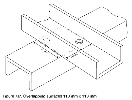
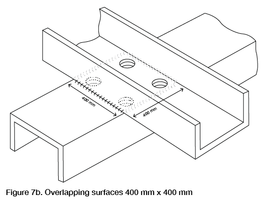
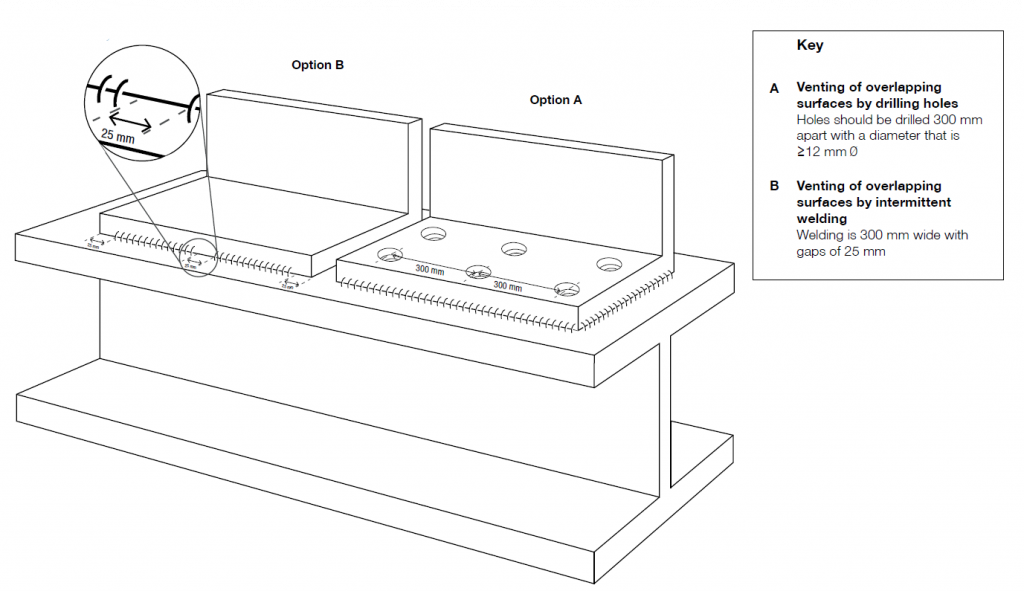 Figure 8. Venting of a large overlapping area
The number and size of holes required to vent an overlapping area takes account of the area of overlap and guidance is provided in Table 2. Ideally holes should be through both sections to aid the free flow of zinc. An alternative is to use intermittent welds but this may result in pretreatment solutions becoming trapped between the overlapping surfaces resulting in seepage staining during service.

Table 2: Guidance on the number and size of holes for venting overlapping areas
Notes
Further guidance is given in EN ISO 14713-2:2020.
*Reproduced courtesy of ISO and/or based on EN ISO 14713-2:2020.
Please note, diagrams are not to scale.
This is part of the series HDG Datasheets and can be requested from Galvanizers Association in a pdf format. Read more about HDG Datasheet 18: Venting and Drainage for Hot Dip Galvanizing.